1 Introduction
This section provides essential information for the end user. For technical details and installation procedures, refer to the Technical Specifications at the end of this document.
2 What is the P20B29 Control Box
The P20B29 is a Joyonway electronic control box for hot tubs, designed for multi-pump systems (up to 4 pumps). It manages massage pumps, heating, filtration, blower, lights, and ozone system. It is located in the hot tub equipment compartment and is connected to the PB553 control panel.
3 Electrical Connection
The electrical installation of the control box must be performed exclusively by a qualified electrician, in compliance with local electrical codes and regulations.
System Requirements
| Requirement | Single Phase | Two/Three Phase |
|---|---|---|
| Voltage | 220-240V~ 50Hz | 220-240V~ 50Hz |
| Residual Current Device | Dedicated 30mA | Dedicated 30mA |
| Circuit Breaker | 32A C curve | 16A per phase |
| Cable Size | 3G4mm² | 4/5G2.5mm² |
| Earth Connection | Mandatory | Mandatory |
DANGER: Do not attempt to make electrical connections yourself. Incorrect wiring can cause electrocution, fire, or irreparable damage to the control box.
Power Supply Type
The P20B29 operates at 220-240V and supports three electrical configurations. The choice depends on the required power and available electrical system.
| Configuration | Voltage | Current | Recommended Use |
|---|---|---|---|
| Single Phase | 220-240V~ | 1x32A | Standard residential installations |
| Three Phase 220V | 220-240V~ | 3x16A | Loads distributed across 3 phases |
NOTE: The P20B29 does NOT support direct 400V power supply. It only operates with 220-240V voltage. If the system is three-phase 400V, phases must be taken to neutral (230V each).
3.1 Standard P20B29 Connection (single-phase 220-240V + earth)
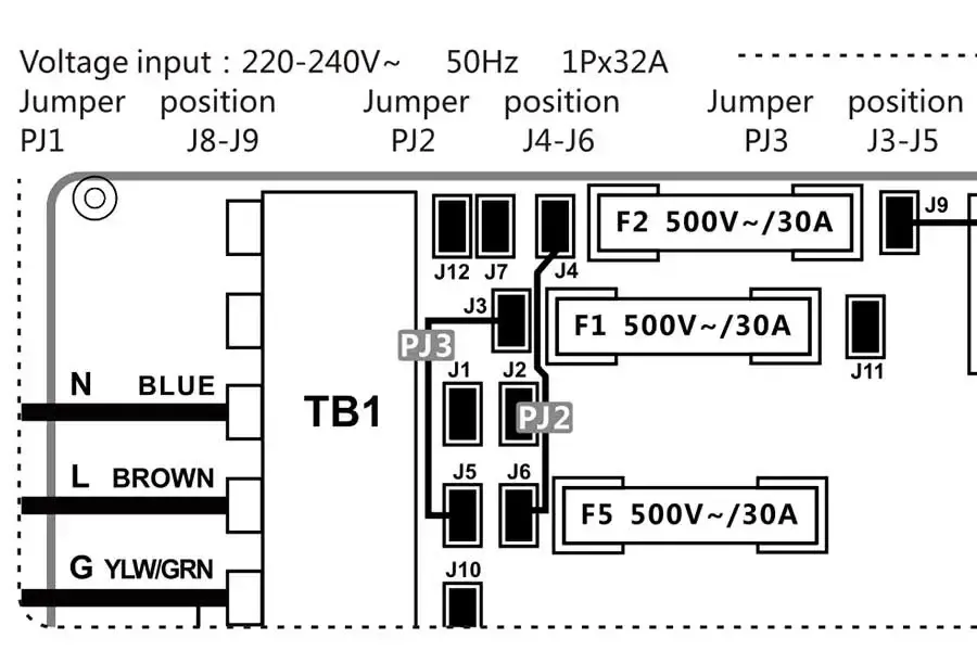
Note: this is the standard configuration and no jumper modifications are required during installation.
3.2 Three-Phase P20B29 Connection
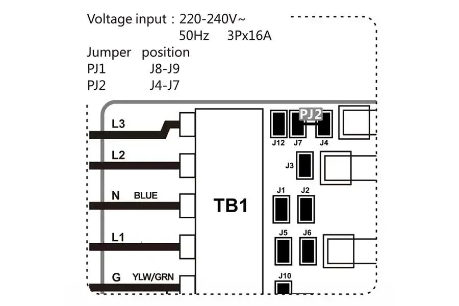
3.3 Jumper Configuration
Electrical configuration is done via jumpers PJ1, PJ2, PJ3 on the board. CONFIGURE BEFORE CONNECTING POWER.
| Configuration | Voltage | Current | PJ1 | PJ2 | PJ3 |
|---|---|---|---|---|---|
| Single Phase | 220-240V~ 50Hz | 1x32A | J8-J9 | J4-J6 | J3-J5 |
| Three Phase | 220-240V~ 50Hz | 3x16A | J8-J9 | J4-J7 | - |
WARNING: Configure jumpers BEFORE connecting power. Incorrect configuration can damage the control box.
Post-Installation Verification
After installation by the technician, verify that:
- The status LED on the control box is lit
- The panel display turns on and shows the temperature
- No error codes appear
- The pumps respond to commands from the panel
- The heater activates when requested
4 Controlled Functions
The P20B29 control box manages up to 4 dedicated pumps plus auxiliary components:
| Component | Function |
|---|---|
| Pump 1 | Main pump (1 or 2 speed) |
| Pump 2 | Secondary pump (1 or 2 speed) |
| Pump 3 | Additional pump (1 or 2 speed) |
| Pump 4 | Additional pump |
| Circulation Pump | Filtration and continuous circulation |
| Blower | Air bubble blower |
| Heater | Water heating |
| Ozone | Ozone sanitization system |
| Light | 12V LED lighting (RGB or white) |
5 Compatible Panels
The P20B29 works with the Joyonway control panel:
| Panel | Type | Notes |
|---|---|---|
| PB553 | LCD with buttons | Standard Joyonway panel |
6 Advanced Technical Information
This section is intended for qualified installers and technicians.
6.1 Product Identification
| Specification | Value |
|---|---|
| Model | P20B29 Control System |
| Version | V1.0 |
| Certifications | CE |
| Target | Multi-pump systems (up to 4 pumps) |
6.2 Electrical Specifications
| Parameter | Value |
|---|---|
| Power Supply | 220-240VAC, 50Hz |
| Single Phase Configuration | 1x32A |
| Three Phase Configuration | 3x16A |
| Frequency | 50Hz |
6.3 System Outputs
| Connector | Device | Max Current |
|---|---|---|
| CN1 | PUMP1 (1/2 SPD) | HIGH: 10A, LOW: 2.5A |
| CN2 | PUMP2 (1/2 SPD) | HIGH: 10A, LOW: 2.5A |
| CN3 | PUMP3 (1/2 SPD) | HIGH: 10A, LOW: 2.5A |
| CN4 | PUMP4 | 10A MAX |
| CN5 | BLOWER | 5A MAX |
| CN6 | CIRC PUMP | 2.5A MAX |
| CN7 | OZONE | 1A MAX |
| CN22 | LIGHT | 12VDC, 2A MAX |
| CN10 | AUX POWER | 1A MAX |
6.4 DIP Switch S1 (A1-A5)
| Switch | ON | OFF |
|---|---|---|
| A1 | HOST SYSTEM | SLAVE SYSTEM |
| A2 | POWER NOT LIMIT | POWER LIMIT |
| A3 | NOT ASSIGNED | NOT ASSIGNED |
| A4 | SETTING | STORE SETTING |
| A5 | CIRC PUMP (Heater Pump) | LOW SPEED PUMP1 (Heater Pump) |
6.5 Fuses
| Fuse | Value |
|---|---|
| F1 | 500V~/30A |
| F2 | 500V~/30A |
| F3 | 250V~/T10A |
| F5 | 500V~/30A |
6.6 Load Configuration Procedure
- Set DIP switch A4 to ON
- Power on the system
- Enter the Set menu on the panel
- Press "-" or "S" for 3 seconds to access Function
- Configure loads (Jets 1-4, Light, Blower, Ozone)
- Return to Set within 60 seconds to save
- Power off and set A4 to OFF
6.7 Supported Light Types
| Type | Wiring |
|---|---|
| 4 wire RGB | B (Blue), G (Green), R (Red), +12V |
| 2 wire | GND, +12V |