1 Introduction
This section provides essential information for the end user. For technical details and installation procedures, refer to the Technical Sheet at the bottom of the document.
2 What is the P23B32 Control Box
The P23B32 is a compact Joyonway electronic control box for hot tubs, with the unique advantage of supporting 400V three-phase power supply in addition to 220-240V. It is ideal for installations where the main line is three-phase 400V. It manages up to 3 pumps, heating, filtration, blower, lights and ozone system.
3 Electrical Connection
The electrical installation of the control box must be performed exclusively by a qualified electrician, in compliance with CEI 64-8 standards and D.M. 37/2008.
System Requirements - Single Phase 220V
| Requirement | Specification |
|---|---|
| Voltage | 220-240V~ 50/60Hz |
| Residual current device | Dedicated 30mA |
| Circuit breaker | 32A curve C |
| Cable section | 3G4mm² (phase + neutral + ground) |
| Grounding | Mandatory |
System Requirements - Three Phase 400V
| Requirement | Specification |
|---|---|
| Voltage | 400V 3N~ 50/60Hz |
| Residual current device | Dedicated 30mA four-pole |
| Circuit breaker | 16A four-pole curve C |
| Cable section | 5G2.5mm² (3 phases + neutral + ground) |
| Grounding | Mandatory |
DANGER: Do not attempt to make electrical connections yourself. 400V voltage is particularly dangerous. Incorrect connection can cause electrocution, fire or irreparable damage to the control box.
Power Supply Type
The P23B32 is the only Joyonway model that supports both 220-240V and 400V three-phase. This flexibility makes it ideal for industrial installations or where the main system is three-phase 400V.
| Configuration | Voltage | Current | Recommended Use |
|---|---|---|---|
| Single phase | 220-240V~ | 1x32A | Standard domestic installations |
| Two phase | 220-240V~ | 2x16A | Loads distributed over 2 phases |
| Three phase 400V | 400V 3N~ | 16A | Industrial systems, native three-phase |
IMPORTANT: Unlike other models, the P23B32 can be connected directly to a 400V three-phase line without transformers. Check the jumper configuration before connection.
3.1 Standard P23B32 Connection (single phase 220-240V + ground)
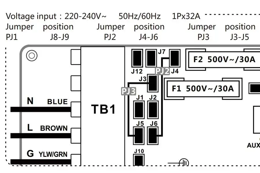
Warning: this is the standard configuration and no jumper modifications are required during installation.
3.2
3.3 Three Phase 400V Connection
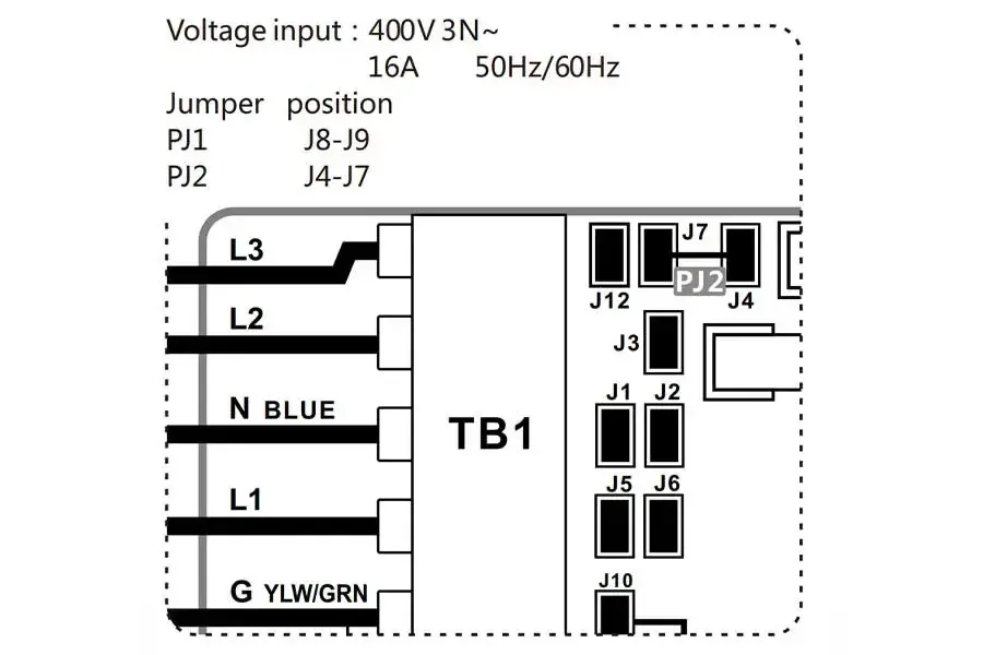
For 400V three-phase connection, modify the jumpers as indicated in the following table BEFORE connecting power.
3.4 Jumper Configuration for Power Supply
Electrical configuration is done via jumpers PJ1, PJ2, PJ3 on the board. CONFIGURE BEFORE CONNECTING POWER.
| Configuration | Voltage | Current | PJ1 | PJ2 | PJ3 |
|---|---|---|---|---|---|
| Single phase | 220-240V~ 50/60Hz | 1x32A | J8-J9 | J4-J6 | J3-J5 |
| Three phase 400V | 400V 3N~ 50/60Hz | 16A | J8-J9 | J4-J7 | - |
WARNING: Configure jumpers BEFORE connecting power. Incorrect configuration, especially at 400V, can cause serious and irreparable damage to the control box and connected components.
Post-Installation Check
After installation by the technician, verify that:
- The status LED on the control box is on
- The panel display turns on and shows the temperature
- No error codes appear
- The pumps respond to panel commands
- The heater activates when requested
4 Controlled Functions
The P23B32 control box manages the following components:
| Component | Function |
|---|---|
| Pump 1 | Main pump (1 or 2 speed) |
| Pump 2 | Secondary pump |
| Pump 3 / Blower | Additional pump OR Blower (configurable) |
| Circulation Pump | Continuous filtration and circulation |
| Heater | Water heating |
| Ozone | Ozone sanitization system |
| Light | 12V LED lighting (max 15W) |
NOTE: Output CN5 can be configured as Blower OR as Pump3 via DIP switch A3. It is not possible to have both simultaneously.
5 Compatible Panels
The P23B32 works with the Joyonway control panel:
| Panel | Type | Notes |
|---|---|---|
| PB553 | LCD with buttons | Standard Joyonway panel |
6 Advanced Technical Information
This section is intended for qualified installers and technicians.
6.1 Product Identification
| Specification | Value |
|---|---|
| Model | P23B32 Control System |
| Version | V1.0 |
| Certifications | CE |
| Target | Compact systems with 400V support |
6.2 Electrical Specifications
| Parameter | Value |
|---|---|
| Single Phase Power | 220-240VAC, 50/60Hz |
| Three Phase Power | 400V 3N~, 50/60Hz |
| Single Phase Configuration | 1x32A |
| Three Phase 400V Configuration | 16A |
| Frequency | 50/60Hz |
6.3 System Outputs
| Connector | Device | Max Current |
|---|---|---|
| CN1 | PUMP1 (1 or 2 SPD) | 10A or HIGH:10A/LOW:2.5A |
| CN2 | PUMP2 | 10A MAX |
| CN5 | BLOWER or PUMP3 | 10A MAX |
| CN6 | CIRC PUMP | 2.5A MAX |
| CN7 | OZONE | 1A MAX |
| CN22 | LIGHT | 12VDC, 15W MAX |
| CN10 | AUX POWER | 1A MAX |
6.4 DIP Switch S1 (A1-A5)
| Switch | ON | OFF |
|---|---|---|
| A1 | HOST SYSTEM | SLAVE SYSTEM |
| A2 | POWER NOT LIMIT | POWER LIMIT |
| A3 | BLOWER OUTPUT (CN5) | PUMP3 OUTPUT (CN5) |
| A4 | SETTING | STORE SETTING |
| A5 | PUMP1 1-SPEED | PUMP1 2-SPEED |
NOTE: DIP A3 determines whether CN5 works as Blower or as Pump3. DIP A5 determines whether Pump1 is 1 or 2 speed.
6.5 Fuses
| Fuse | Value |
|---|---|
| F1 | 500V~/30A |
| F2 | 500V~/30A |
| F3 | 250V~/T10A |
6.6 Load Configuration Procedure
- Set DIP switch A4 to ON
- Turn on the system
- Enter the Set menu on the panel
- Press "-" or "S" for 3 seconds to access Function
- Configure the loads (Jets 1-3, Light, Blower, Ozone)
- Return to Set within 60 seconds to save
- Turn off and set A4 to OFF
6.7 Supported Light Types
| Type | Wiring |
|---|---|
| 4 wire RGB | B (Blue), G (Green), R (Red), +12V |
| 2 wire | GND, +12V |
6.8 Recommended Applications
- Installations with native three-phase 400V system
- Compact hot tubs (2-3 pumps)
- Situations requiring Blower/Pump3 flexibility
- International installations (50/60Hz support)