1 Environment Preparation
Before proceeding with the Finnish Sauna installation, it is necessary to properly prepare the environment that will host it.
1.1 Space and Floor Requirements
| Requirement | Specification |
|---|---|
| Minimum room height | 190 cm |
| Floor | Flat, leveled, load-bearing |
| Level tolerance | ±2 mm/meter |
| Recommended materials | Tiles, treated wood, resin |
1.2 Room Ventilation
For optimal sauna operation it is necessary to ensure proper air exchange:
- Lower air intake (if provided): Hole behind the heater for clean air inflow
- Upper air outlet: Grill at the top for hot air outflow
1.3 Safety Distances
Respect the following minimum distances from the heater:
| Element | Minimum Distance |
|---|---|
| Electrical junction boxes | 50 cm |
| Rear wall | See model table |
| Floor | 15-18 cm |
1.4 Drain Installation
Installing a drain is not mandatory or necessary.
2 General Electrical Requirements
WARNING: Electrical connection must be performed exclusively by qualified personnel according to current regulations.
2.1 Electrical Line Characteristics
The Finnish Sauna produces heat through an electric resistance heater. For electrical connections it is mandatory:
- Copper cable with R2 class insulation (temperatures up to 80°C)
- Dedicated line with differential circuit breaker (safety switch)
- Efficient grounding
- Compliance with regulations
NOTE: Electrical cables must not be spliced for extension inside the sauna. Any junction boxes must be at least 50 cm from the heater.
3 Resistance Heater Installation
The heart of the Finnish Sauna is the electric resistance heater with lava stones. It can be used on single-phase or three-phase systems depending on the model and power.
3.1 Available Heater Models
| Model | Power | Power Supply | Electrical Line | Safety Switch | Sauna Volume |
|---|---|---|---|---|---|
| BL-ASHEAT3 | 3 kW | 220-240V Single-phase | 3x4 mm² | Yes | 2-4 m³ |
| BL-ASHEAT45 | 4.5 kW | 220-240V Single / 380V Three-phase (on request) | 3x6 mm² / 5x4 mm² | Yes | 3-6 m³ |
| BL-ASHEAT6 | 6 kW | 220-240V Single / 380V Three-phase (on request) | 3x6 mm² / 5x4 mm² | Yes | 5-9 m³ |
| BL-ASHEAT9 | 9 kW | 380V Three-phase | 5x6 mm² | Yes | 9-13 m³ |
NOTE: The choice of electrical power supply mode (single-phase/three-phase) does not invalidate the warranty, but the warranty does not cover damages resulting from incorrect power supply configuration.
3.2 Positioning and Thermal Distances
| Model | Distance from Floor | Dimensions (LxWxH mm) |
|---|---|---|
| BL-ASHEAT3 | 15-18 cm | 305x205x480 |
| BL-ASHEAT45 | 15-18 cm | 410x280x560 |
| BL-ASHEAT6 | 15-18 cm | 410x280x560 |
| BL-ASHEAT9 | 15-18 cm | 410x280x580 |
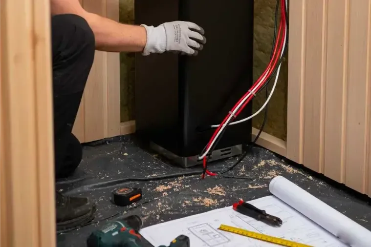
3.3 Heater Installation Procedure
- Verify that the power supply is off
- Mount the heater on the wall using the provided screws
- Respect the distances indicated in the table above
- Remove all protective plastic parts applied for shipping
- Proceed with electrical connection
DANGER: DO NOT install the heater in humid, wet, frozen environments, or where corrosive, flammable elements and fuels in general are present.
3.4 Heater Electrical Connection
Open the door closed by a screw, then proceed with the connections as indicated:
3.4.1 Single-Phase Connection (BL-ASHEAT3/45/6)
Connect to terminals 1-2-3-4-5-6:
- Terminal 1: G (Ground)
- Terminal 2: Bridge to N
- Terminal 3: N (Neutral)
- Terminal 4: Bridge to L1
- Terminal 5: L1 (Phase 1)
- Terminal 6: Bridge to L1
3.4.2
3.4.3 Lamp and Services Connection (Terminals 7-8-9-10)
- Terminal 7: N for internal lamp
- Terminal 8: L for internal lamp
- Terminal 9: N for services
- Terminal 8: L for services
3.4.4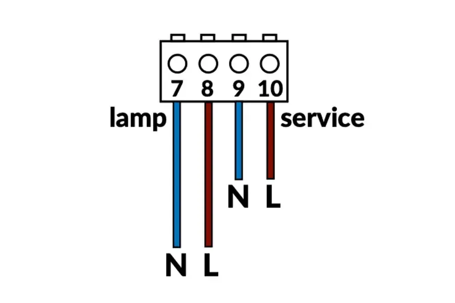
3.4.5 Three-Phase Connection (BL-ASHEAT45/6/9)
Connect to terminals 1-2-3-4-5-6:
- Terminal 1: G (Ground)
- Terminal 2: Bridge to N
- Terminal 3: N (Neutral)
- Terminal 4: L1 (Phase 1)
- Terminal 5: L2 (Phase 2)
- Terminal 6: L3 (Phase 3)
NOTE: BL-ASHEAT3 is available only in single-phase version.

3.5 Lava Stones Quantity and Placement
Correct stone positioning is fundamental for heater durability and efficiency.
| Heater Model | Stone Quantity | Stone Dimensions |
|---|---|---|
| BL-ASHEAT3 | 12 kg | 3-8 cm |
| BL-ASHEAT45 | 18 kg | 3-8 cm |
| BL-ASHEAT6 | 18 kg | 3-8 cm |
| BL-ASHEAT9 | 20 kg | 3-8 cm |
3.5.1 Positioning Procedure
- Rinse the stones under running water to remove dust and dirt
- Select FLAT stones and position them between the resistances without forcing
- Insert all flat stones in the lower part
- Use rounded stones to create an upper layer that covers the resistances
- DO NOT force the stones on the resistances laterally or from above
- Make sure the resistances are not visible from above
WARNING: Do not add more stones beyond those supplied. Water poured on the stones must evaporate quickly without reaching the underlying resistances, to avoid harmful thermal shocks.
4 Controller and Commands Connection
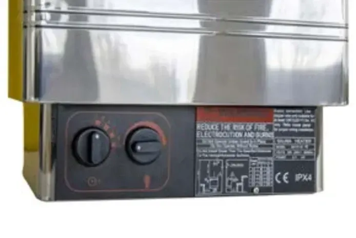
The heater control is integrated and equipped with two analog knobs:
4.1 Available Controls
- Left Knob (Timer): Turns on the heater and sets the time (max 90 minutes). Shutdown is automatic.
- Right Knob (Temperature): Regulates the resistance power and consequently the sauna temperature.
NOTE: The control graphics may vary according to production needs, but the commands remain those indicated.
4.2 Lighting and Chromotherapy
The sauna has:
- Emergency and service light
- Chromotherapy (optional): controlled by separate switch
5 First Start-up
5.1 Pre-Start Checks
- Verify that all electrical connections have been correctly made
- Check correct positioning of lava stones
- Remove any plastic protections
- Verify structure integrity
- Check ventilation operation
5.2 First Start-up Procedure
- Turn the left knob (Timer) to maximum
- Turn the right knob (Temperature) to 3/4 of the stroke
- Wait a few minutes and verify temperature increase
- Check on the thermometer the effective heating
- Verify absence of anomalous odors (a slight odor is normal in the first hours of use)
- Adjust the temperature to the desired value
NOTE: Each sauna requires its own time to reach operating temperature, depending on: cabin volume, room temperature, humidity, heater power.