1 Introduction
This section provides essential information for the end user. For technical details and installation procedures, refer to the Technical Specifications at the end of this document.
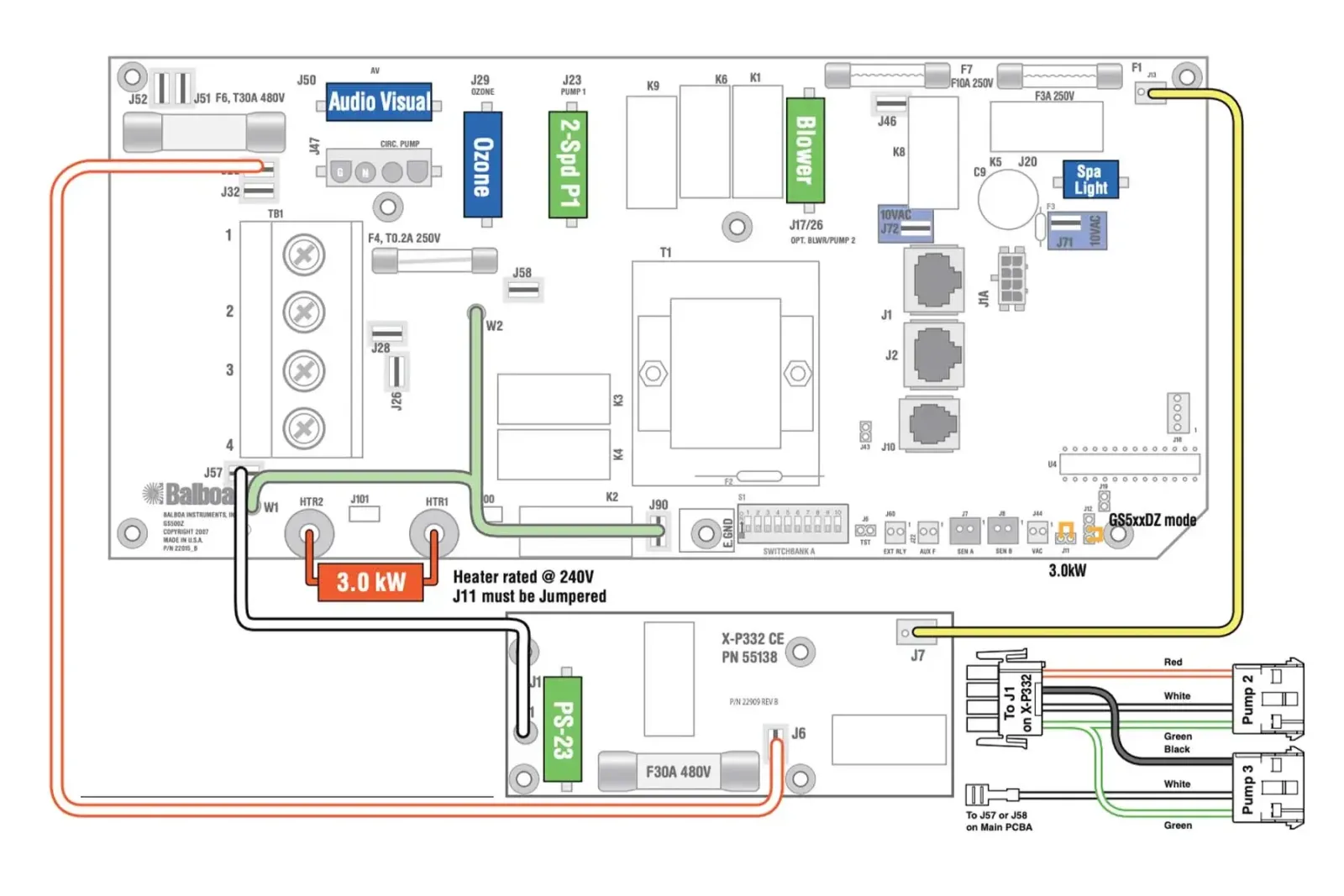
2 What is the GS523DZ Control Box
The GS523DZ belongs to the Balboa GS series, a simpler line of control boxes compared to the BP series. It manages massage pumps, heating, filtration, lights, blower, and ozone system. It is located in the hot tub equipment compartment and is connected to VL series panels (VL801D, VL802D) with segmented LCD displays.
3 Electrical Connection
The electrical installation of the control box must be performed exclusively by a qualified electrician, in compliance with local electrical codes and regulations.
System Requirements
| Requirement | Single Phase | Three Phase 400V |
|---|---|---|
| Power Supply | 230V~ 50Hz | 400V 3N~ 50Hz |
| Residual Current Device | Dedicated 30mA | 30mA four-pole |
| Circuit Breaker | 32A C curve (max 40A) | 16A per phase (max 20A) |
| Cable Size | 3G4mm² | 5G2.5mm² |
| Earth Connection | Mandatory | Mandatory |
| Panel-to-Tub Distance | Minimum 3 meters | Minimum 3 meters |
DANGER: Do not attempt to make electrical connections yourself. Incorrect wiring can cause electrocution, fire, or irreparable damage to the control box.
Power Supply Type
The GS523DZ supports various electrical configurations, including three-phase 400V (requires PCB Rev B).
| Configuration | Voltage | Current | Recommended Use |
|---|---|---|---|
| Single Phase (Single Service) | 230V~ | 1x32A | Standard residential installations |
| Dual Phase (Dual Service) | 230V~ | 2x16A | Loads distributed across 2 lines |
| Three Phase 400V (3-Phase) | 400V 3N~ | 16A per phase | Industrial installations, native three-phase |
IMPORTANT: The three-phase 400V configuration requires PCB Rev B and the connection MUST include neutral (phase-to-neutral voltage 230V). See the technical section for wiring instructions.
3.1 Standard GS523DZ Connection (single-phase 220-240V + earth)
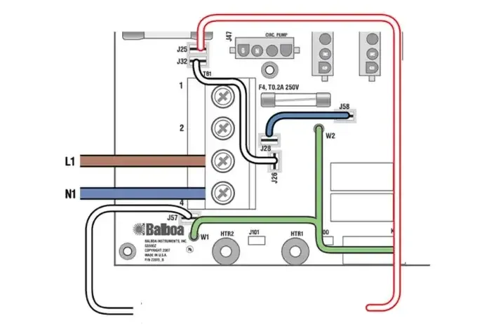
Note: this is the standard configuration and no modifications are required during installation.
Post-Installation Verification
After installation by the technician, verify that:
- The status LED on the control box is lit
- The panel display turns on and shows the temperature
- No error codes appear
- The pumps respond to commands from the panel
- The heater activates when requested
4 Controlled Functions
The GS523DZ control box manages the following components:
| Component | Function |
|---|---|
| Pump 1 | Main massage pump (2 speed) |
| Pump 2 | Secondary massage pump |
| Pump 3 | Additional pump |
| Circulation Pump | Continuous filtration (Setup 2 only) |
| Blower | Air bubble blower |
| Heater | Water heating (3kW) |
| Ozone | Ozone sanitization system |
| Light | Tub lighting (10V) |
| A/V | Audio/video output |
5 Compatible Panels
The GS523DZ works with the following Balboa VL series control panels:
| Panel | Part Number | Type |
|---|---|---|
| VL801D | 54121 | Segmented LCD |
| VL802D | 54562 | Segmented LCD |
NOTE: VL series panels have a segmented LCD display, different from the graphic displays of TP panels. The interface is simpler but still complete for basic functions.
6 Advanced Technical Information
This section is intended for qualified installers and technicians.
6.1 Product Identification
| Specification | Value |
|---|---|
| Model | GS523DZ |
| System PN | 54763-01 |
| System Model | GS5-GS523DZ-RCA-3.0 |
| Software Version | 43 |
| Release Year | 2009 |
| Available Setups | 2 |
| Series | GS (vs BP) |
6.2 Electrical Specifications
| Parameter | Value |
|---|---|
| Single Phase Power | 230VAC, 50Hz, 1x32A |
| Dual Phase Power | 230VAC, 50Hz, 2x16A |
| Three Phase Power | 400VAC 3N~, 50Hz, 16A per phase (requires PCB Rev B) |
| Heater Power | 3.0kW @ 240V |
6.3 Three-Phase 400V Configuration (3-Phase Service)
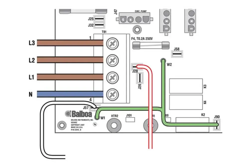
The three-phase configuration requires PCB Rev B and the following wiring modifications:
- Completely remove the white wire from J26 and J32 (or J25)
- Completely remove the blue wire from J28 and J58
- Connect the 3 phases (L1, L2, L3), neutral (N), and earth (PE)
Three-phase load distribution:
| Phase | Loads |
|---|---|
| L1 | Heater |
| L2 | Expansion boards (optional) |
| L3 | Pump 1, Blower, main board equipment |
IMPORTANT: The connection MUST include neutral with phase-to-neutral voltage of 230VAC.
6.4 System Outputs
| Output | Voltage | Notes |
|---|---|---|
| Pump 1 | 230V | 2-Speed |
| Pump 2 | 230V | 1-Speed |
| Pump 3 | 230V | 1-Speed |
| Blower | 230V | - |
| Ozone | 230V | - |
| Circ Pump | 230V | Setup 2 only |
| Spa Light | 10V | - |
| A/V | 230V | - |
| Heater | - | 3.0kW |
6.5 Setup Reference Table (2 Configurations)
| Setup | Circ Pump | Pump 1 | Pump 2 | Pump 3 | Blower | Ozone |
|---|---|---|---|---|---|---|
| 1 | - | 2-Spd 230V | 1-Spd 230V | 1-Spd 230V | 230V | 230V |
| 2 | 230V | 2-Spd 230V | 1-Spd 230V | 1-Spd 230V | 230V | 230V |
NOTE: The key difference between Setup 1 and Setup 2 is the presence of a dedicated Circ Pump. In Setup 1, filtration occurs via Pump 1 low speed.
6.6 DIP Switch S1 (A1-A10)
| Switch | OFF | ON |
|---|---|---|
| A1 | Normal Operation | Test Mode |
| A2 | Normal | 16A Total |
| A3 | Not Assigned | Not Assigned |
| A4 | Not Assigned | Not Assigned |
| A5 | Pump 1 2-Speed | Pump 1 1-Speed |
| A6 | 50Hz | 60Hz |
| A7 | J17/26 Disabled | J17/26 Enabled |
| A8 | Celsius (C) | Fahrenheit (F) |
| A9 | Normal Circ Mode | 24hr Circ Mode |
| A10 | Normal | 20A Total |
6.7 Important Jumpers
| Jumper | Position | Function |
|---|---|---|
| J11 | 2 PIN | Heater 3kW or higher |
| J11 | 1 PIN | Heater 2.5kW or lower |
| J12 | - | Software selection (DO NOT MODIFY) |
| J43 | CLOSED | Reset Persistent Memory |
WARNING: Do not modify J12. Incorrect modification can render the system unusable.
6.8 Memory Reset
To restore factory settings (different from BP series):
- Disconnect the power supply
- Close jumper J43
- Reconnect the power supply
- Wait for the reset
- Disconnect the power supply
- Open jumper J43
- Reconnect the power supply
6.9 Additional Options
- Dolphin Remote - Wireless remote control
- IR Receiver Module - Infrared receiver
- MoodEFX / FiberEFX Lighting - Advanced lighting systems
- Expander Board X-P332 CE - Expansion board