1 Introduction
This section provides essential information for the end user. For technical details and installation procedures, refer to the Technical Specifications at the end of this document.
2 What is the BP6013G2 and BP6013G3 Control Box
The electronic control box that manages all hot tub functions: massage pumps, heating, filtration, lights, and ozone system. It is located in the hot tub equipment compartment and is connected to the control panel used to manage the functions. It is the model with the highest number of available configurations.
3 Electrical Connection
The electrical installation of the control box must be performed exclusively by a qualified electrician, in compliance with local electrical codes and regulations.
System Requirements
| Requirement | Specification |
|---|---|
| Power Supply | 230V single phase or three phase 230V, 50/60Hz |
| Residual Current Device | Dedicated 30mA (Type A or AC) |
| Circuit Breaker | 32A C curve (single phase) or 16A triple pole (three phase) |
| Single Phase Cable Size | 3G4mm² (live + neutral + earth) |
| Three Phase Cable Size | 5G2.5mm² (3 phases + neutral + earth) |
| Earth Connection | Mandatory |
| Panel-to-Tub Distance | Minimum 3 meters |
DANGER: Do not attempt to make electrical connections yourself. Incorrect wiring can cause electrocution, fire, or irreparable damage to the control box.
Power Supply Type
The BP6013G2/G3 supports various electrical configurations. The choice depends on power consumption and available electrical system.
| Configuration | Voltage | Current | Recommended Use |
|---|---|---|---|
| Single Phase | 230V~ | 1x32A | Standard residential installations |
| Three Phase | 230V 3~ | 3x16A | Loads distributed across 3 phases (from 400V line) |
NOTE: In three-phase configuration, the BP6013G2 uses three phases at 230V (taken to neutral from a 400V three-phase line). Loads are distributed across the three phases to balance consumption.
3.1 Standard BP6013G2 Connection (single-phase 220-240V + earth)
3.1.1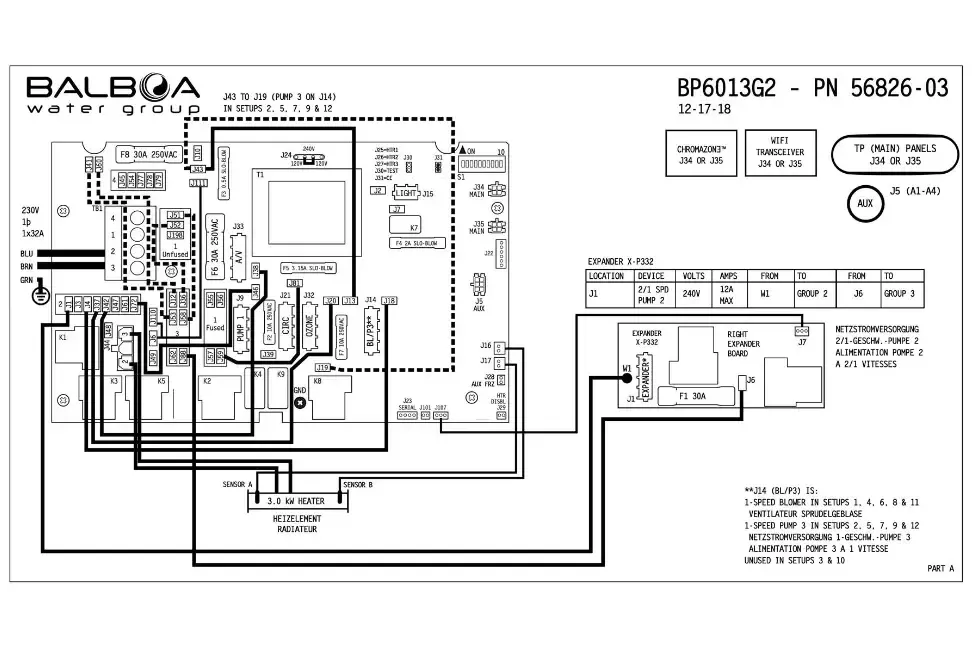
Note: this is the standard configuration and no modifications are required during installation.
3.2 Standard BP6013G3 Connection (single-phase 220-240V + earth)
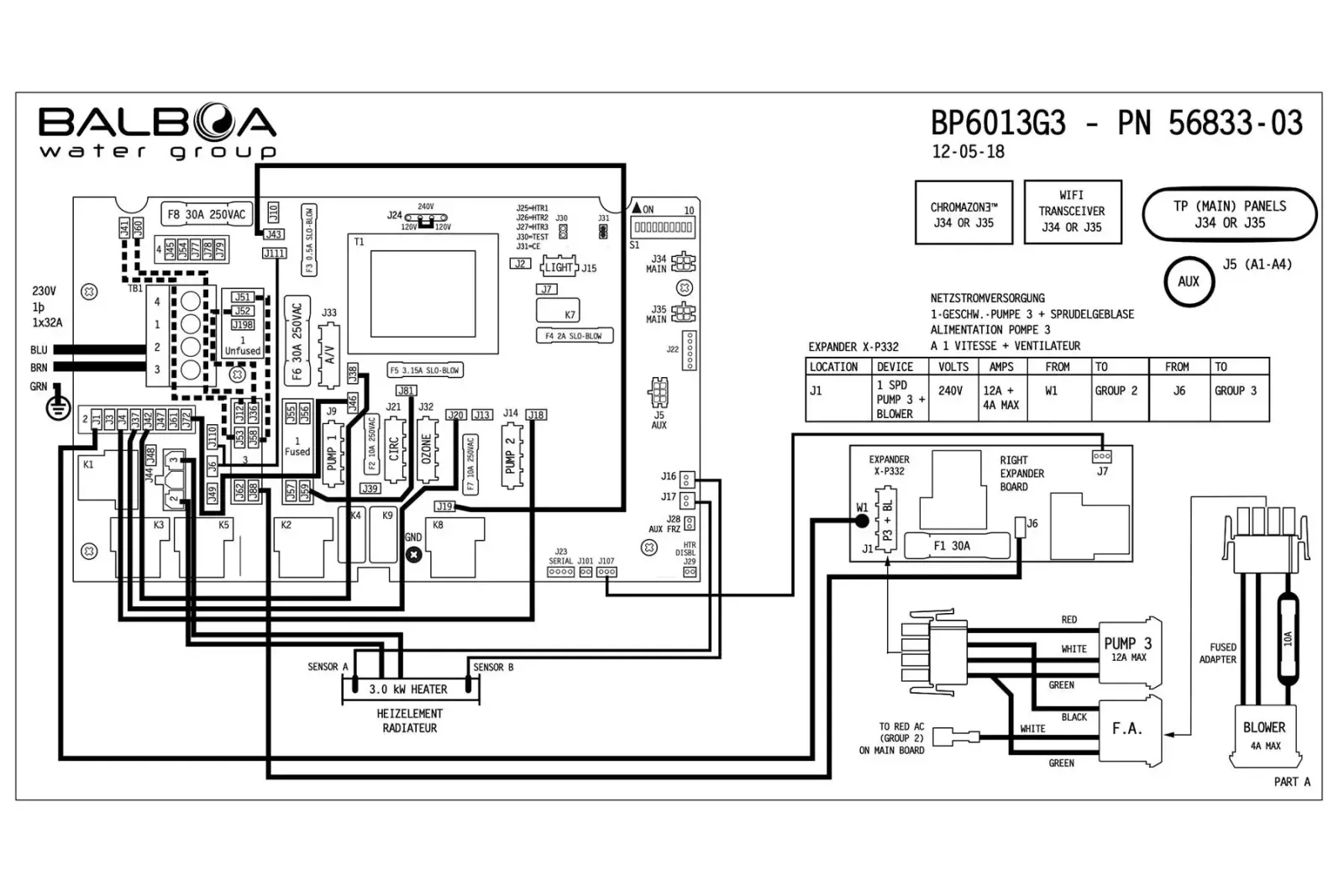
Note: this is the standard configuration and no modifications are required during installation.
3.3 Multi-Phase Connection (three-phase 380V + Neutral + Earth)
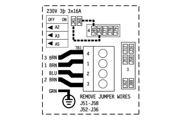
Disconnect the electrical power supply. To switch to the three-phase system, make these modifications to the wire jumpers, to change from the configuration in the image above to the one on the left.
- remove the jumper between J52 and J62
- remove the jumper between J51 and J88
- remove the jumper between J41 and J12
- remove the jumper between J60 and J36
- apply the jumper between J60 and J45
- apply the jumper between J41 and J79
- on DIP switch S1: set A2 to ON
- on DIP switch S1: set A3 to ON
- on DIP switch S1: set A5 to OFF
Reconnect the electrical power supply. The control box will repeat the automatic initialization functions (requires approximately 5 minutes).
Post-Installation Verification
After installation by the technician, verify that:
- The status LED on the control box is lit (solid green)
- The panel display turns on and shows the temperature
- No error codes appear
- The pumps respond to commands from the panel
- The heater activates when requested
4 Controlled Functions
The BP6013G2 and BP6013G3 control boxes can manage the following components (depending on hot tub configuration):
| Component | Function |
|---|---|
| Pump 1 | Main massage pump (1 or 2 speed) |
| Pump 2 | Secondary massage pump (1 or 2 speed) |
| Pump 3 | Additional pump (if present) BP6013G3 only |
| Circulation Pump | Filtration and continuous circulation |
| Blower | Air bubble blower |
| Heater | Water heating (2kW or 3kW) |
| Ozone | Ozone sanitization system |
| Light | LED tub lighting |
5 Advanced Technical Information
This section is intended for qualified installers and technicians. It contains technical specifications, configurations, and installation procedures.
5.1 Product Identification
5.1.1 BP6013G2
| Specification | Value |
|---|---|
| Model | BP6013G2 |
| Part Number (Incoloy 3kW) | 56826-03 |
| Part Number (Titanium 3kW) | 56827-03 |
| Part Number (Incoloy 2kW) | 56978-01 |
| Software Version | 43.0 |
| Release Year | 2017 |
| Available Setups | 12 |
5.1.2 BP6013G3
| Specification | Value |
|---|---|
| Model | BP6013G3 |
| Part Number (Incoloy 3kW) | 56833-03 |
| Part Number (Titanium 3kW) | 56834-03 |
| Software Version | 43.0 |
| Release Year | 2018 |
| Available Setups | 9 |
5.2 Electrical Specifications
| Parameter | Value |
|---|---|
| Power Supply | 230VAC, 50/60Hz |
| Heater Power | 2.0kW or 3.0kW @ 240VAC |
| Single Phase Configuration | 1x32A |
| Three Phase Configuration | 3x16A (from 400V line) |
5.3 System Outputs
| Output | Description | Max Current |
|---|---|---|
| Pump 1 | 1 or 2 speed | 12A |
| Pump 2 | 1 or 2 speed | 12A |
| Pump 3 | 1 speed | 12A |
| Circ Pump | 1 speed | 2A |
| Blower | 1 speed | 4A |
| Ozone | - | 0.5A |
| Spa Light | 10VAC | 2A |
| A/V | 230VAC | 3A |
| Heater | 2.0/3.0kW @ 240VAC | - |
5.4 Compatible Panels
| Panel | Compatibility |
|---|---|
| spaTouch2 | Yes |
| TP900 | Yes |
| TP800 | Yes |
| TP600 | Yes |
| TP400 | Yes |
5.5 Setup Reference Table
5.5.1 BP6013G2 (12 Configurations)
| Setup | Circ Pump | Pump 1 | Pump 2 | Pump 3 | Blower |
|---|---|---|---|---|---|
| 1 | Prog. Filt. + Polling | 2-Speed | 2-Speed | - | 1-Speed |
| 2 | Prog. Filt. + Polling | 2-Speed | 2-Speed | 1-Speed | - |
| 3 | Prog. Filt. + Polling | 2-Speed | 2-Speed | - | - |
| 4 | Prog. Filt. + Polling | 2-Speed | 1-Speed | - | 1-Speed |
| 5 | Prog. Filt. + Polling | 2-Speed | 1-Speed | 1-Speed | - |
| 6 | Prog. Filt. + Polling | 1-Speed | 1-Speed | - | 1-Speed |
| 7 | Prog. Filt. + Polling | 1-Speed | 1-Speed | 1-Speed | - |
| 8 | None | 2-Speed | 2-Speed | - | 1-Speed |
| 9 | None | 2-Speed | 2-Speed | 1-Speed | - |
| 10 | None | 2-Speed | 2-Speed | - | - |
| 11 | None | 2-Speed | 1-Speed | - | 1-Speed |
| 12 | None | 2-Speed | 1-Speed | 1-Speed | - |
NOTE: Setups 1-7 include Circ Pump with programmable filtration and polling. Setups 8-12 use Pump 1 low speed for filtration. Unlike the BP6013G3, Pump 2 can be configured as 2-Speed (setups 1-3, 8-10).
5.5.2 BP6013G3 (9 Configurations)
| Setup | Circ Pump | Pump 1 | Pump 2 | Pump 3 | Blower |
|---|---|---|---|---|---|
| 1 | Prog. Filt. + Polling | 2-Speed | 1-Speed | 1-Speed | 1-Speed |
| 2 | Prog. Filt. + Polling | 2-Speed | 1-Speed | 1-Speed | - |
| 3 | Prog. Filt. + Polling | 2-Speed | 1-Speed | - | 1-Speed |
| 4 | Prog. Filt. + Polling | 1-Speed | 1-Speed | 1-Speed | 1-Speed |
| 5 | Prog. Filt. + Polling | 1-Speed | 1-Speed | 1-Speed | - |
| 6 | Prog. Filt. + Polling | 1-Speed | 1-Speed | - | 1-Speed |
| 7 | None | 2-Speed | 1-Speed | 1-Speed | 1-Speed |
| 8 | None | 2-Speed | 1-Speed | 1-Speed | - |
| 9 | None | 2-Speed | 1-Speed | - | 1-Speed |
NOTE: Setups 1-6 include Circ Pump with programmable filtration and polling. Setups 7-9 use Pump 1 low speed for filtration.
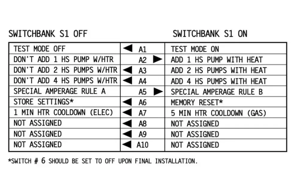
5.6 DIP Switch S1 (A1-A10)
| Switch | OFF | ON |
|---|---|---|
| A1 | Normal Operation | Test Mode |
| A2 | Normal | Add 1 HS pump w/ heater |
| A3 | Normal | Add 2 HS pumps w/ heater |
| A4 | Normal | Add 4 HS pumps w/ heater |
| A5 | Special Amperage Rule A | Special Amperage Rule B |
| A6 | Store Settings | Memory Reset |
| A7 | Cooling Time 1 min (electric) | Cooling Time 5 min (gas) |
| A8 | Not Assigned | Not Assigned |
| A9 | Not Assigned | Not Assigned |
| A10 | Not Assigned | Not Assigned |
5.7 Setup Selection Procedure
- Disconnect the power supply
- Open the control box cover
- Locate the setup selection jumpers
- Configure the desired setup according to the table
- Close the cover
- Reconnect the power supply
- Verify on the panel that the configuration is correct
5.8 Test Mode
Test Mode (DIP A1 ON) allows you to verify the operation of all components:
- Set DIP A1 to ON
- Power on the system
- All components can be manually activated
- Verify pumps, blower, lights, ozone
- When finished, set DIP A1 to OFF
- Restart the system
5.9 Memory Reset
To restore factory settings:
- Disconnect the power supply
- Set DIP A6 to ON
- Reconnect the power supply
- Wait for the MEM RSET message on the display
- Disconnect the power supply
- Set DIP A6 to OFF
- Reconnect the power supply
6 Expansions
6.1 X-P332 Expander Board
Adds additional outputs for advanced configurations. Supports CHROMAZON3 for advanced RGB LED chromotherapy.
6.2 Auxiliary Panels
- AX10 - Basic auxiliary panel
- AX20 - Intermediate auxiliary panel
- AX40 - Advanced auxiliary panel
6.3 Bluetooth
- bba - Balboa Bluetooth Adapter (first generation)
- bba2 - Balboa Bluetooth Adapter 2 (second generation)