1 Introduction
This section provides essential information for the end user. For technical details and installation procedures, refer to the Technical Specifications at the end of this document.
2 What is the BP200G1 Control Box
The BP200G1 is the entry-level electronic control box from the Balboa BP series. It manages the basic functions of the hot tub: massage pumps, heating, filtration, lights, and ozone system. It is located in the hot tub equipment compartment and is connected to the control panel. With 3 available setups, it is ideal for simple configurations.
3 Electrical Connection
The electrical installation of the control box must be performed exclusively by a qualified electrician, in compliance with local electrical codes and regulations.
System Requirements
| Requirement | Specification |
|---|---|
| Power Supply | 230V single phase, 50Hz |
| Residual Current Device | Dedicated 30mA (Type A or AC) |
| Circuit Breaker | 20A C curve |
| Cable Size | 3G2.5mm² (live + neutral + earth) |
| Earth Connection | Mandatory |
| Panel-to-Tub Distance | Minimum 3 meters |
DANGER: Do not attempt to make electrical connections yourself. Incorrect wiring can cause electrocution, fire, or irreparable damage to the control box.
Power Supply Type
The BP200G1 operates exclusively in single-phase 230V configuration. It does not support three-phase configurations.
| Configuration | Voltage | Current | Recommended Use |
|---|---|---|---|
| Single Phase | 230V~ | 1x20A | Standard residential installations |
NOTE: The BP200G1 is designed for compact systems with limited power. For installations requiring more power or three-phase configuration, consider the BP6013G2 or BP6013G3 model.
3.1 Standard BP200G1 Connection (single-phase 220-240V + earth)
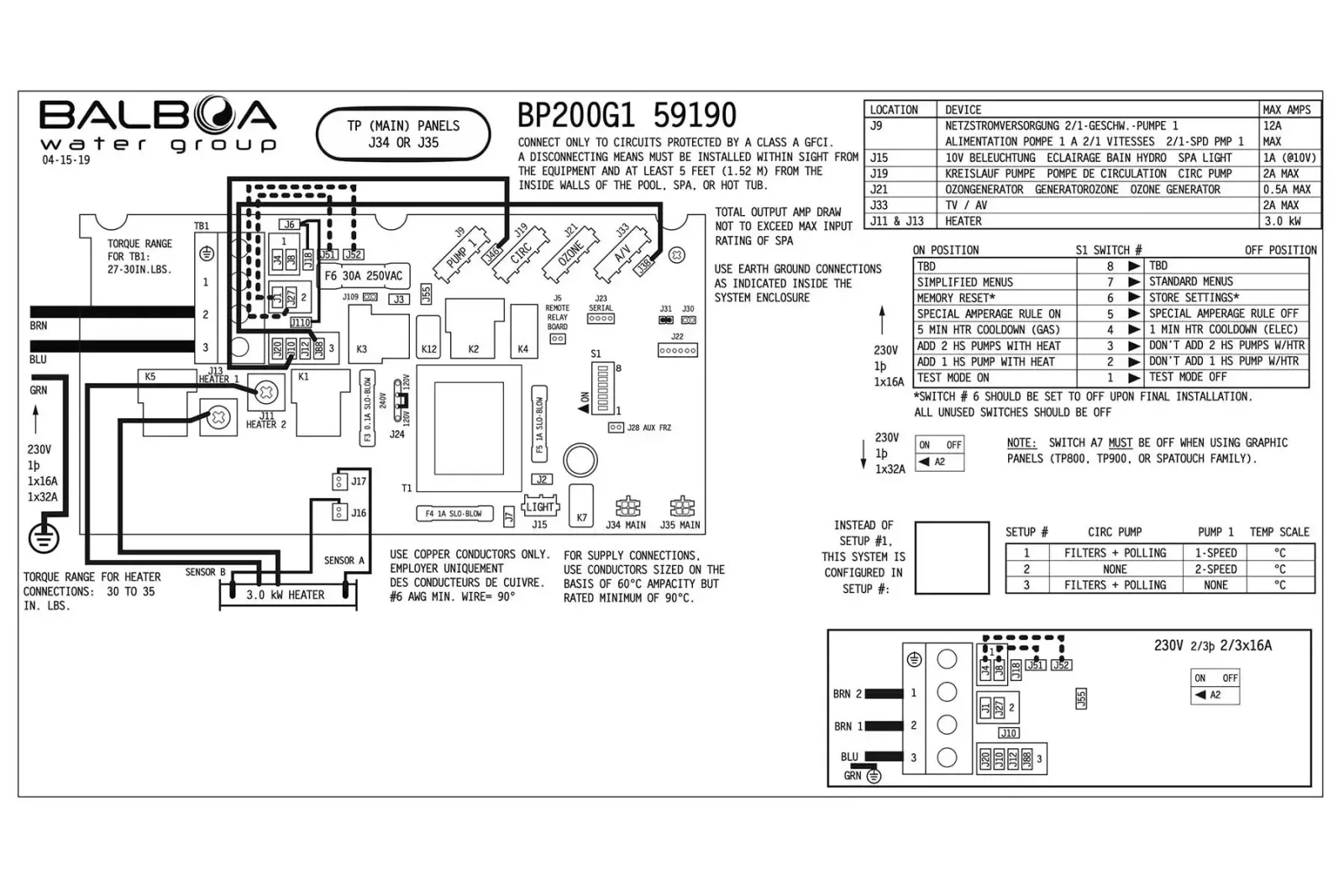
Note: this is the standard configuration and no modifications are required during installation.
After installation, verify that:
- The status LED on the control box is lit (solid green)
- The panel display turns on and shows the temperature
- No error codes appear
- The pumps respond to commands from the panel
- The heater activates when requested
4 Controlled Functions
The BP200G1 control box can manage the following components (depending on hot tub configuration):
| Component | Function |
|---|---|
| Pump 1 | Main massage pump (1 or 2 speed) |
| Pump 2 | Secondary massage pump |
| Circulation Pump | Filtration and continuous circulation |
| Blower | Air bubble blower |
| Heater | Water heating (3kW) |
| Ozone | Ozone sanitization system |
| Light | LED tub lighting |
5 Compatible Panels
The BP200G1 works with the following Balboa control panels:
| Panel | Type | Notes |
|---|---|---|
| TP600 | LCD with buttons | Standard display |
| TP500 | LCD with buttons | Standard display |
| TP400 | LCD with buttons | Compact display |
NOTE: The BP200G1 does not support touchscreen panels (spaTouch) or advanced panels (TP800, TP900).
6 Advanced Technical Information
This section is intended for qualified installers and technicians. It contains technical specifications, configurations, and installation procedures.
6.1 Product Identification
| Specification | Value |
|---|---|
| Model | BP200G1 |
| Part Number (2kW) | 56485-04 |
| Software Version | 42 |
| Release Year | 2015 |
| Available Setups | 3 |
| Series | BP (entry-level) |
6.2 Electrical Specifications
| Parameter | Value |
|---|---|
| Power Supply | 230VAC, 50Hz |
| Heater Power | 3.0kW @ 230VAC |
| Configuration | Single Phase 1x20A |
| Max System Power | 4.6kW |
6.3 System Outputs
| Output | Description | Max Current |
|---|---|---|
| Pump 1 | 1 or 2 speed | 12A |
| Circ Pump | 1 speed | 2A |
| Ozone | - | 0.5A |
| Spa Light | 10VAC | 1A |
| Heater | 3.0kW @ 240VAC | - |
6.4 Setup Reference Table (3 Configurations)
| Setup | Circ Pump | Pump 1 | Temp Scale |
|---|---|---|---|
| 1 | Prog. Filt. + Polling | 1-Speed | °C |
| 2 | No | 2-Speed | °C |
| 3 | Prog. Filt. + Polling | 2-Speed | °C |
6.5 DIP Switch S1 (A1-A8)
| Switch | OFF | ON |
|---|---|---|
| A1 | Normal Operation | Test Mode |
| A2 | Not Assigned | Adds 1 HS pump (or air pump) with heater |
| A3 | Not Assigned | Adds 1 2HS pump (or 1HS and air pump) with heater |
| A4 | 1 minute heater shutoff | 5 minute heater shutoff |
| A5 | Special Amperage Rules OFF | Special Amperage Rules ON |
| A6 | Store Settings | Memory Reset |
| A7 | Standard Menu | Simplified Menu |
| A8 | TBD | TBD |
6.6 Setup Selection Procedure
- Disconnect the power supply
- Open the control box cover
- Locate the setup selection jumpers
- Configure the desired setup according to the table
- Close the cover
- Reconnect the power supply
- Verify on the panel that the configuration is correct
6.7 Test Mode
Test Mode (DIP A1 ON) allows you to verify the operation of all components:
- Set DIP A1 to ON
- Power on the system
- All components can be manually activated
- Verify pumps, blower, lights, ozone
- When finished, set DIP A1 to OFF
- Restart the system
6.8 Memory Reset
To restore factory settings:
- Disconnect the power supply
- Set DIP A6 to ON
- Reconnect the power supply
- Wait for the MEM RSET message on the display
- Disconnect the power supply
- Set DIP A6 to OFF
- Reconnect the power supply