1 Introduction and Planning
Proper preparation of the installation site is essential to ensure optimal operation and long-term durability of the hot tub. Before proceeding with final positioning, the main preparations must be planned and completed: electrical supply, possible water connection, and base preparation. Careful planning at this preliminary stage avoids future problems and reduces installation costs.
WARNING: Preparations should be completed before the hot tub delivery.
2 Choosing the Location
2.1 General Criteria
Choosing the optimal position for the hot tub must take into account several factors:
- Accessibility for delivery and positioning (check passage width, gate height, presence of stairs)
- Proximity to electrical connections (shorter distance=lower preparation costs)
- Sun exposure
- Privacy and protection from prevailing wind
- Adequate structural load capacity (for installations on terraces, floors, and similar)
- Easy access for routine and extraordinary maintenance
2.2 Preliminary Checks
Before proceeding with preparations, verify:
- Municipal building regulations (possible need for permits or notifications)
- Condominium regulations (for installations in condominium settings)
- Landscape or environmental constraints of the area
- Presence of underground utilities (gas pipes, water, sewers, buried electrical cables)
3 Electrical Preparation
3.1 Power Cable Characteristics
Prepare a dedicated power cable from the main electrical panel to the hot tub installation point. The cable must have a cross-section of 4 mm² or 6 mm² based on the power absorbed by the hot tub and the distance from the electrical panel.
| Hot Tub Power | Distance from Electrical Panel | Recommended Cable Section |
|---|---|---|
| 3 kW | Up to 20 meters | 4 mm² |
| 3 kW | 20-35 meters | 6 mm² |
| 3 kW | Over 35 meters | 10 mm² |
| 5 kW | Up to 20 meters | 6 mm² |
| 5 kW | Over 20 meters | 10 mm² |
3.2 Cable Type and Installation
Use copper cable with insulation suitable for the installation type:
- Underground installation: FG7OR or FG7OR1 cable in double-wall corrugated conduit, minimum depth 50 cm, mechanical protection with tiles or warning tape
- Outdoor exposed installation: FG7OR cable in corrugated conduit or UV-resistant trunking, fastening every 30-40 cm
- Indoor installation: N07V-K cable in corrugated conduit under plaster or in trunking
3.3 Upstream Protection
Install a dedicated combined circuit breaker with residual current device for the hot tub in the main electrical panel:
- Type: combined thermal-magnetic + residual current device (RCD)
- Thermal-magnetic rated current: 16A (for hot tubs up to 3 kW) or 25A (for hot tubs up to 5 kW)
- Trip curve: C
- Residual current: Type AC or A, rated operating current 30 mA
- Breaking capacity: minimum 4.5 kA (6 kA recommended)
DANGER: The 30 mA residual current device is legally mandatory for protecting people against indirect contact. Powering the hot tub without this protection is not permitted. The absence of a residual current device poses a serious danger to people's lives.
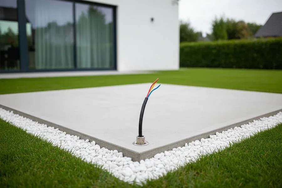
3.4 Cable Arrival Point
The cable must arrive in the immediate vicinity of the hot tub's technical compartment (within 1 meter). Leave at least 50-70 cm of extra cable to allow connection to the control box terminals without mechanical stress. Do not make joints or extensions along the power cable route.
3.5 Reference Standards
Electrical preparation must comply with:
- CEI 64-8 Section 702 Standard: Special environments and applications - Pools and fountains
- Ministerial Decree 37/2008: Regulation of installation work in buildings
- CEI 64-8 Part 5 Standard: Selection and installation of electrical components
NOTE: Electrical preparation must be carried out by a licensed electrician, who will issue the declaration of conformity according to Ministerial Decree 37/2008 upon completion. Keep this document with the hot tub documentation.
4 Water Preparation
4.1 Standard Valves
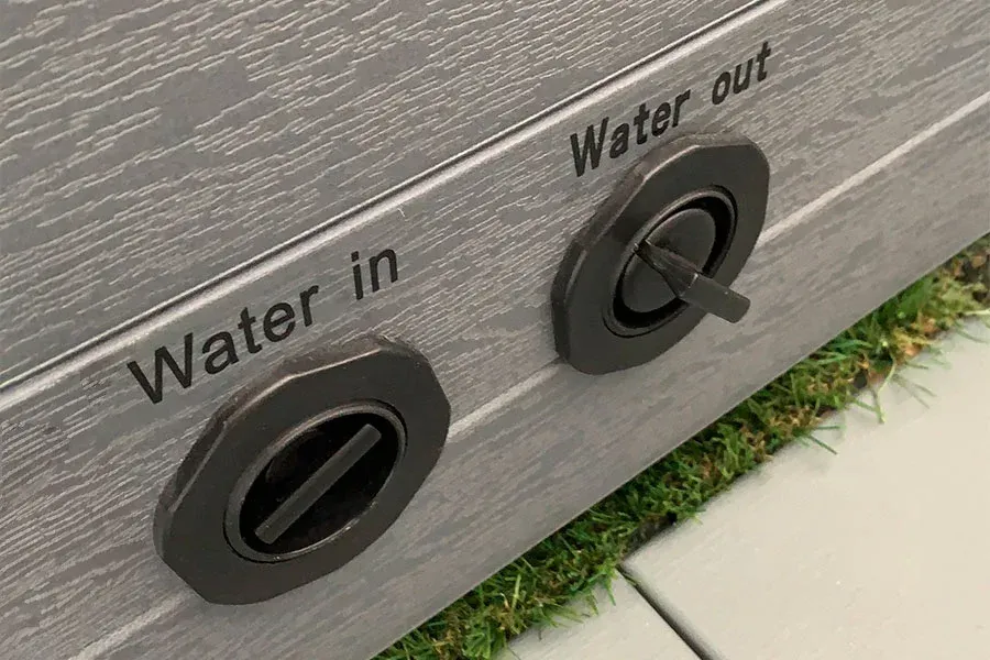
The hot tub comes standard with two side valves positioned on the shell:
- WATER IN valve (water inlet): 1/2" or 3/4" female threaded valve for filling the tub
- WATER OUT valve (water drain): 1/2" or 3/4" female threaded valve for emptying the tub
Both valves are designed for connection with a common garden hose (1/2" or 3/4" garden hose with quick-connect fittings). This solution is the simplest and most economical, suitable when frequent use of the hot tub is not planned.
4.2 Direct Water Supply Connection
For more practical and professional use, a direct water supply connection can be prepared, eliminating the need to manually connect the garden hose each time.
Direct connection requirements:
- Polyethylene PE or multilayer pipe to the WATER IN valve
- Pipe diameter: DN 20 (3/4") recommended for adequate flow rate
- Ball shut-off valve installed upstream (for maintenance)
- Pressure reducer if mains pressure exceeds 3 bar (recommended range 1.5-2.5 bar)
- Sediment filter before the hot tub inlet (not mandatory)
With direct connection, the standard manual valve installed on the hot tub can be bypassed and the prepared pipe connected directly to the internal hydraulic circuit. This modification requires technical intervention and may affect the warranty: consult the manufacturer before proceeding.
4.3 Drain Preparation
Two solutions are possible for water drainage:
Solution 1 - External hose drain (standard solution):
- Connect a garden hose to the WATER OUT valve
- Direct the water to a collection pit, green area, or stormwater disposal system
- Required hose length: to be assessed based on distance from drain point
- Provide adequate slope (minimum 1-2%) to ensure gravity flow
Solution 2 - Fixed drain with trap (professional solution):
- Prepare DN 50 (50 mm diameter) drain pipe from the WATER OUT valve to the drain point
- Install an accessible trap to prevent odor backflow
- Final connection to inspection pit or sewer system (check local regulations for pool water discharge)
- Minimum slope 2% along the entire route
WARNING: Check local regulations for pool water discharge. Some municipalities prohibit discharge to the sewer of water containing chlorine or other disinfectants without proper treatment. In such cases, a neutralization system or settling times must be provided before discharge.
4.4 Cold Water Supply Only
Only a cold water connection needs to be prepared, as the hot tub is equipped with an autonomous electric heater capable of bringing the water to the desired temperature. Preparing a hot water supply connection is neither necessary nor recommended, as it would involve:
- Higher preparation costs
- Unnecessary consumption of hot water produced by the boiler
- Possible temperature incompatibility with hot tub components
- Greater limescale formation due to hot water
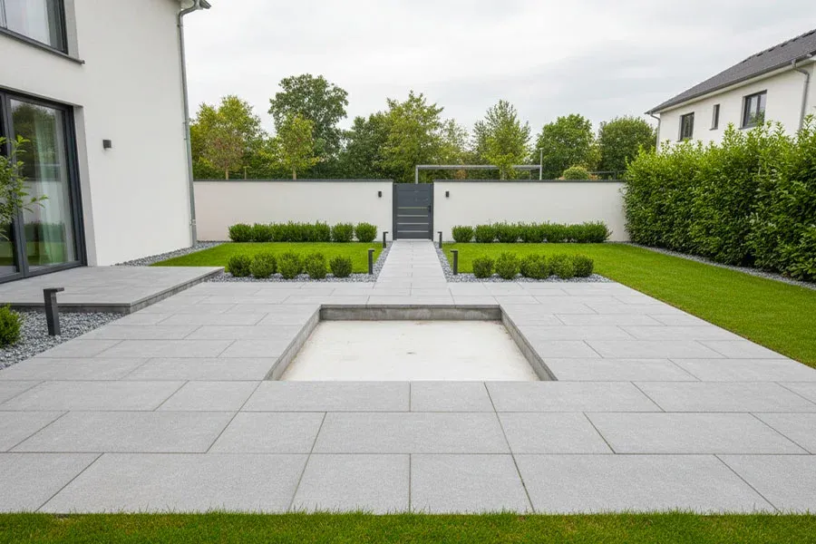
5 Base Preparation
5.1 General Requirements
The base must provide a stable, level support surface capable of bearing the weight of the hot tub full of water with people inside. The total weight can range from 1,500 kg to 5,000 kg depending on the model and capacity.
Required characteristics:
- Flatness: maximum level tolerance of 5 mm across the entire surface (check with laser level or precision spirit level)
- Stability: no structural settlement or subsidence over time
- Load capacity: adequate for the total weight of the hot tub (verify with structural engineer for installations on floors)
- Drainage: avoid water pooling under the hot tub
5.2 Solution 1: Natural Compact Ground
If the laying ground is naturally compact and stable, it is NOT mandatory to build a concrete slab. This solution is possible when:
- The ground is compact clay or sandy (verify absence of settlement with load test)
- There are no roots, protruding stones, or obvious irregularities
- The area is not subject to water pooling or flooding
- The ground is level or can be leveled with minor earthworks
Procedure for laying on compact ground:
- Carefully level the laying area with maximum tolerance of 5 mm
- Remove stones, roots, weeds, and any protruding elements
- Spread a layer of fine gravel or washed sand 3-5 cm thick
- Compact with vibrating plate or manual roller
- Check leveling again with spirit level
- Lay geotextile TNT (non-woven fabric) 300-500 g/m² to protect the bottom of the hot tub and prevent vegetation growth
NOTE: The layer of fine gravel or sand serves to fill any small remaining irregularities in the ground and create a uniform support surface. Always compact this layer before laying the geotextile.
5.3 Solution 2: Concrete Slab
Building a reinforced concrete slab represents the most professional and durable solution, recommended for permanent installations or on ground that is not perfectly stable.
Slab dimensions:
- Minimum dimension: equal to the external dimensions of the hot tub
- Recommended dimension: 30-50 cm overhang per side beyond the hot tub, to create a perimeter walkway and facilitate maintenance access
- Minimum thickness: 10-12 cm for hot tubs up to 2,000 kg, 15-20 cm for hot tubs over 2,000 kg
Slab stratigraphy:
- Excavation to a depth of 30-35 cm
- Compacted crushed stone layer 15 cm thick (drainage sub-base)
- Leveling sand layer 5 cm thick
- Polyethylene sheet for ventilated crawl space (vapor barrier)
- Welded mesh 6 mm, 20x20 cm grid, positioned at mid-thickness of the slab
- Concrete pour Rck 25-30 N/mm² (class C25/30) to the desired thickness
- Surface leveling with screed rail and float
- Minimum curing of 20-25 days before hot tub positioning
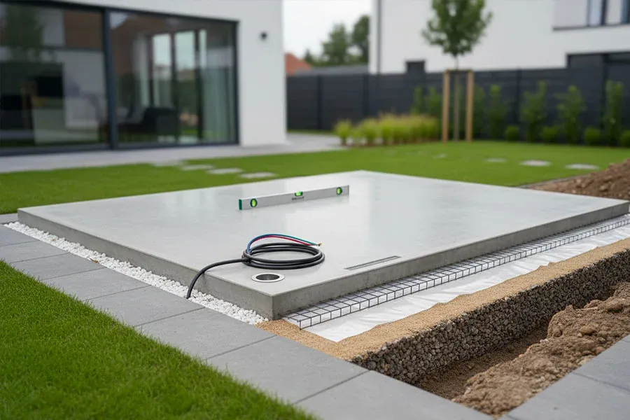
WARNING: The slab must be level. Slopes or depressions cause uneven weight distribution, resulting in abnormal stress on the hot tub shell and possible cracks or breaks over time. Check leveling at multiple points with a precision level.
5.4 Solution 3: Lightweight Screed or Interlocking Paving
Intermediate solutions between natural ground and concrete slab:
Lightweight screed:
- Cement mix with lightweight aggregates (expanded clay, perlite)
- Thickness 8-10 cm on compacted sub-base
- Suitable for temporary or semi-permanent installations
- Low cost, quick installation times
Interlocking paving:
- Concrete blocks 6-8 cm thick
- Laid on 3-5 cm sand bed
- Compacted crushed stone sub-base 15 cm
- Pleasant aesthetic appearance, possibility of recovering blocks
- Medium-high cost, requires careful laying to ensure leveling
6 Structural Checks for Installation on Floors
DANGER: Installing a hot tub on terraces, balconies, or building floors MANDATORILY requires structural verification by a licensed engineer or architect. Never proceed with installation without this verification, at the risk of partial or total floor collapse with serious consequences.
6.1 Floor Structural Load Capacity
Residential floors are generally designed to support an accidental load of 200 kg/m² (Italian standard NTC 2018). Floors of modern buildings can reach 400-450 kg/m², but this data must be verified by a licensed technician by analyzing the building's original structural design.
6.2 Hot Tub Weight
The total weight to consider includes:
- Empty weight of the hot tub: 100-800 kg (depending on model and materials)
- Water weight: tub volume in liters (e.g., 1,500 liters=1,500 kg)
- Weight of people: consider 4-6 people x 70 kg/person=280-420 kg
- Snow load (if outdoor installation): assess based on climate zone (0-200 kg/m²)
Indicative total weight: 2,000-liter hot tub + 4 people=100 kg (tub) + 2,000 kg (water) + 280 kg (people)=2,380 kg total
Load per square meter: 2,380 kg / occupied surface area m² (e.g., 2x2 m hot tub=2,380 / 4=595 kg/m²)
In the example above, the load is HIGHER than the standard load capacity of a residential floor (200 kg/m²), so installation is NOT possible without structural reinforcement work.
6.3 Required Technical Assessment
The structural engineer must verify:
- Type of floor (hollow clay-concrete, precast slab, self-supporting, wood, steel)
- Dimensions and spacing of load-bearing beams/joists
- Material characteristics (concrete strength, steel)
- Load class provided in the original design
- Presence of existing superimposed loads
- Possible need for structural reinforcement
- Load distribution method (point supports on load-bearing beams)
NOTE: Never rely on approximate or "eyeball" assessments. Only a structural verification with calculations can determine the feasibility of safe installation. The cost of this verification is negligible compared to the risk of collapse.

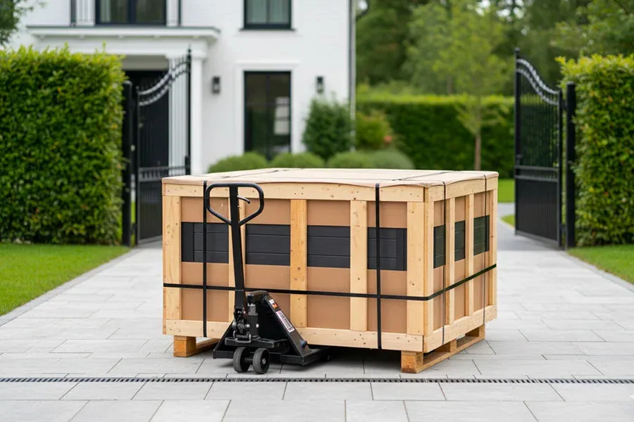
7 Access and Handling
7.1 Access Path
Verify that the access path from the public road to the installation location allows passage of the packaged hot tub.
If the path has insurmountable restrictions, consider alternative solutions such as:
- Lifting with mobile crane (check maneuvering space and reach)
- Lifting by helicopter (for isolated mountain locations or historic centers)
- Passage through neighboring properties (with prior agreement from owners)
7.2 Maneuvering Area
Provide an adequate maneuvering area at the unloading point to allow the delivery vehicle to approach and unload the hot tub:
- Minimum space in front of the laying area: 4-5 meters for positioning with manual pallet truck
- Load-bearing surface for heavy vehicles: mobile crane up to 3.5 tonnes, check ground or pavement load capacity
- No overhead obstacles: electrical cables, branches, canopies.
8 Preparation Checklist
Before confirming the hot tub delivery date, verify completion of all preparations:
8.1 Electrical Preparation
- Adequate cross-section power cable laid to the installation point
- 30 mA combined circuit breaker with residual current device installed in the electrical panel
- System conformity declaration issued by licensed electrician
- Residual current device operation verified
- 50-70 cm cable slack at arrival point
8.2 Water Preparation
- Cold water point available within 5 meters of the hot tub (garden hose) OR direct connection prepared
- Drain point identified and prepared (if fixed drain)
- Adequate slope toward drain point verified
- Pool water discharge authorization verified with local regulations
8.3 Base Preparation
- Laying surface leveled
- Base built (concrete slab) or ground prepared (gravel/sand + geotextile)
- Structural verification performed by technician (if installation on floor)
- Slab curing completed
- Area clear of materials, equipment, debris
8.4 Accessibility
- Access path verified and clear
- Gates/doors open or keys available for carriers
- Any mobile crane booked and maneuvering area verified
- Public land occupation permits obtained (if required)
WARNING: Carriers do not wait for work to be completed: any failed deliveries due to incomplete preparations will be charged to the customer.